 Hands
On Physics
The Great Bungee Jump
Core Project
Step 2: Building the Electronics
Overview. This page details one way to make the electronic measurements
needed for the Great Bungee Jump.
1. Make the circuit.

Figure C5
Timing Circuit
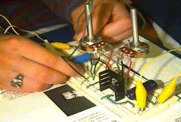
Assemble the circuit shown below. This is identical to the circuit in
Messing Around Investiation 3, except without the jumpers you used for
switches there. This time, use R1 = 1 Mohm (brown, black, green).
C1 = 1 mF (microfarad.)
Figure M9
Timing Circuit
You will recall that when switch 1 is closed, the meter will read zero.
This is because this switch (S1) makes a direct connection between the
voltmeter leads, so there can be no voltage difference between these leads.
The capacitor will start charging through the resistor when switch one
(S1) opens, and stop charging when switch two (S2) opens. When both switches
are open, the capacitor and voltmeter are isolated from the power supply.
Any charge in the capacitor is trapped there, because there is no easy
way for it to get out except by leaking through the capacitor or voltmeter.
2. Make S2. S2 is the trip wire at the bottom of the drop. When
the trip wire is in place, it contucts electricity, and S2 is closed. When
the falling mass hits the trip wire, it knocks out the wire and breaks
the circuit, opening the switch.
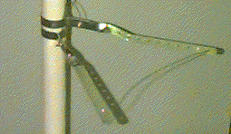
Bend the two metal pipe hangers as shown below. Attach 1.8 m of green hook-up
wire to each hanger. The wire can be slipped under the screw used to tighten
the hanger to the pipe. Slip the hangers onto the vertical pipe so that
the flat straps are near, but do not touch each other. Adjust the
screw on each hanger so you can slide them on the pipe, but they stay firmly
in place. You can now stand the tower in the base and tape it into position.
Arrange the hangers as shown in the photo and lay a wire with bare ends
across them. Test the switch with a falling mass using the continuity
test found in most multimeters.

Figure C2
Stopping Switch
3. Make S1. On the bungee jump scale model, S1 is made from contacts
on a clothespin at the top of the tower. The mass that drops is part of
this switch. As soon as you release the mass, the switch opens.
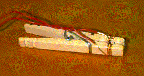
Cut two lengths of red hook-up wire about 1.8 m long. Make one contact
of S1 by stripping about 5 cm on one end of one wire and wrap it around
the narrow part of one jaw of the spring clothespin. Repeat with the other
wire on the other jaw of the clothespin. Be sure that these wires do not
touch when the clothespin "jaws" are closed.

Figure C1
Starting Switch
Using a hose clamp, fasten one of the long arms of the clothespin to
the side of the 30 cm pipe section. Attach this to the top of the tower
with a 90° PVC elbow. Tape these parts together so that he mass will
drop cleanly from the jaws of the clothespin and hits the trip wire. Test
the switch with the mass but do not let it drop yet.
4. Complete the circuit. Position your tower so you can safely reach
the top. Place the circuit on a nearby table. Connect S1 to the circuit
board using the red wires and S2 using the green wires.
Where the mass will hit the floor, place foam or something soft to protect
the floor.
Test allignment by clipping the mass into the clothespin at the top and
positioning the trip wire across the hangers. You need to adjust the position
of switch 2 so that the wire is knocked off of the hangers by the falling
weight. Caution! Do not drop the weight on your partner!
5. Test the circuit. Apply power to the circuit. With the mass clipped
in S1 your voltmeter should read zero. If it does not, check the connections
on the clothespin and the way it is attached to the circuit. When the meter
reads zero, drop the mass. After the drop, the meter should give a steady
reading of a few hundred mV. When your tower and circuit are working, try
several drops. Is the voltage almost the same for each drop? How much does
it vary? What percentage is this variation?
Congratulations! You now have a working bungee jump model and are close
to being able to investigate the physics of the Great Bungee Jump! But
before you do, you need to ensure that your timer is accurate.
Previous Page || Up a Level || Index || Next Page