 Hands On Physics
Haze
Core Project Activities
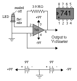
How the Sun Photometer Works:
Pictured below in Figure C1, is an electronic circuit diagram of the Sun
Photometer. The triangle marked "741" is an operational amplifier.
In operation, light from the sun causes the LED detector to generate a tiny
electrical current much like a solar cell does. This signal is amplified
and read with a voltmeter.

The core activity of this unit is building
a sun photometer.
This task has been broken down into several sequential activities which
lead to a completed scientific instrument for measuring haze in the atmosphere.
Sun Photometer Assembly Instructions
As soon as the sun photometer has been assembled, you can begin taking data.
To make the data usable, however, this photometer must be calibrated.
How to Calibrate the Sun Photometer
A well-build and properly calibrated sun photometer is a scientific instrument
which can be used repeatedly for gathering information about haze.
Using and Maintaining the Sun
Photometer
Previous Page || Up
a Level || Index || Next
Page