 |
Hands-On-Physics
ELECTRICITY
|
Messing
Around
|
- A Circuit -
|
Circuits are collections of electronic parts (components) connected in webs.
Real circuits are usually represented on paper as circuit diagrams.
These electronic "blueprints" are used around the world for designing,
understanding, and documenting real circuits.

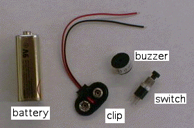
Figure M6
Components for the circuit
In this activity you will learn to connect electronic components in complete
circuits. You will begin to understand how to read
circuit diagrams and
how to draw your own.
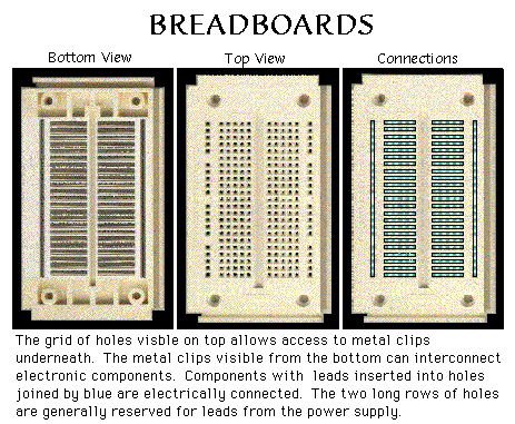
A solderless bread board makes it easy to hook up and dismantle circuits without
soldering. Adjacent holes in each rowof five are connected (inside the bread board).
The rows are not connected across the central groove.
The holes in each bus (the outside strips that run the length of the board) are also
connected. See the pictures below.

Figure M7
Solderless bread board
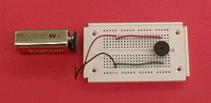
A picture of the circuit, without a switch, is shown below.

Figure M8
Buzzer on board
Follow these steps to make a simple circuit.
- Use the solderless breadboard to connect a battery,battery clip, and buzzer in a complete circuit. Make the buzzer buzz.
- Reverse the buzzer. Does it still work?
- Notice the indicators for the positive terminal on the battery and on
the buzzer. Think of positive charge being pushed from the
positive terminal of a battery and drawn back to the negative terminal of the battery.
The positive terminal is usually red and the negative terminal is usually black.
Current flows out of the positive terminal of the battery and into the positive
terminal of a circuit component, through the component, out its negative terminal
and finally returns to the negative terminal of the battery.
Warning: Current flows from negative to positive through batteries but
current flows from positive to negative through other circuit components.
- Take a normally open ( N.O.) switch and include it in your circuit. Try
different ways until the switch turns the buzzer on and off.
- Replace your N.O. switch with a normally closed ( N.C.) switch.
What happens?
Circuit diagrams use symbols to simplify and clarify pictures of circuits.
Wires are symbolized
by simple straight lines. Each electronic component has it own symbol,
as shown below.

Figure M9
Symbols
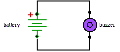
A circuit diagram for the circuit without a switch is shown below.

Figure M10
Simple circuit diagram
For Reporting
- Sketch your buzzer circuit, including an indication of
the positive terminals on the battery and the buzzer.
- Draw two circuit diagrams, one for your circuit with a
NC switch and another with a N.O. switch.
Previous Page ||
Up a Level ||
Index ||
Next Page