 |
Hands-On-Physics
ELECTRICITY
|
Messing
Around
|
- Bulbs in Circuits -
|
The simplest way to connect electronic components in a circuit is to connect
them in a chain, one after the other. To complete a circuit the circle must
be closed by connecting the last component to the first. A simple circle of
components is called a series circuit. All the current flows through every
component.
For the next activities you will need to understand
circuit diagrams.
In this activity you will first make a simple series circuits with light bulbs.
After that you will connect the bulbs in more complicated circuits
Follow these steps to make series circuits.
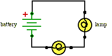
- Use the solderless bread board to connect small light bulbs in series,
as shown in the circuit diagram. You will have to solder leads onto the sockets
so you can attach them to the breadboard.

Figure M11
Series Circuit
- If you add a third bulb to the circuit, what do you think will happen
to the brightness of the bulbs? Try it and see.
- Think about the charge leaving the battery and circulating through
each bulb. Why does adding a third bulb change things?
Measuring current (amps) with a voltmeter.
A voltmeter can be made into an ammeter by attaching it across a one-ohm
resistor.
( I = V / R , so if the resistance = 1, the voltage reading = current)
Put the one-ohm resistor in the circuit where you want to measure current.
The current measurement equals the voltage drop across the one-ohm resistor.
A circuit with branches is called a parallel circuit. At a branch point the
current splits onto smaller currents that go through two or more electronic
components "in parallel" and then combine at another branch point. The current
continues through the rest of the circuit back to its starting place.
Follow these steps to make branched (parallel) circuits.
- Wire two bulbs as shown in the circuit diagram below. Notice that soon after
the current leaves the battery, it comes to a branch point and splits. The two
bulbs are connected in parallel, so each gets only part of the main current.

Figure M12
Parallel circuit
- Think about the charges from the battery going through the two paths.
Compare the brightness of these bulbs to the bulbs in series. What will
happen if you make a third path by adding a third bulb in parallel?
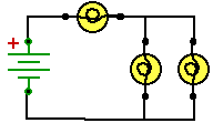
- Wire a combination circuit, shown in the circuit diagram below. Note
the relative brightness of the bulbs. Predict what will happen to the remaining
bulbs when you remove any one of them. Verify your predictions.

Figure M13
Combination Circuit
- Measure the voltage drop across each bulb and the voltage produced by
the battery. Record the voltages.
- Use your multimeter with the 1 ohm resistor to measure the current through
each bulb and through the battery. Record the currents.
For Reporting
- Remeasure the voltages and currents in the combination circuit.
Make the following measurements with all the bulbs lit:
- The voltage maintained by the battery.
- The voltage drop across each bulb (3).
- The current through the battery.
- The current through each bulb (3).
- Why are bulbs brighter in a parallel circuit than a series circuit?
Use the words 'voltage' and 'current' in your answer.
- Which will drain a battery faster, a series or parallel circuit?
Explain your answer.
Previous Page ||
Up a Level ||
Index ||
Next Page