 |
Hands-On-Physics
ELECTRICITY
|
Messing
Around
|
- Transistor Circuit -
|
Many security systems work by setting off an alarm when
a door is opened or a window is broken. In these systems there is a conductor
at these points that breaks, just like a N.C. switch. In this activity you
will be building a circuit that sets off an alarm when broken. To save your--or
your teacher's!--sanity, you may replace the buzzer with a light bulb.
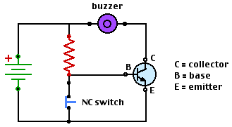
In this activity you will make an alarm circuit. In this circuit, a N.O. switch
is replaced with a N.C. switch and a NPN transistor.

Figure M14
Circuit components
Use a transistor to control this circuit. A transistor allows
a small current to trigger a larger one. When there is no
current through the base (B) the buzzer is off, as if the transistor
were an open switch. When there is a small current into the base, a large current
can flow into the collector and out the emitter; the
transistor acts like a closed switch, and the buzzer buzzes.
Buzzer Controlled by a Transistor

Figure M15
Transistor circuit
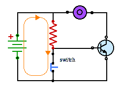
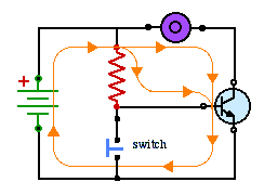
Study the diagrams below and look at the paths of the current. First with the
switch closed and then with the switch open.

Figure M16
Current with switch closed
Because the switch is closed, voltage between the the base and the emitter is zero.
It takes a voltage about 0.6 V to cause any current to flow into the base.

Figure M17
Current with switch open
Follow these steps to make an alarm circuit.
Use your resistor code reader
to pick three values of resistance to try in the circuit. Choose resistors
that are far apart in value.
A resistor resists the flow of charge.
In this circuit, it keeps too much charge from running
into the base of the transistor. Note that without the resistor there would
be a short circuit with the switch closed.
- Build this circuit on your circuit board, using your 'medium' resistor.
- Try a higher resistance. Does it still work? Why?
- Try a lower resistance. Does it still work? Why?
For Reporting
- Why use a transistor for this circuit instead of a simple switch?
- Why did the circuit work with different resistors? Which resistor
makes the most sense to use and WHY?
- Redraw the circuit diagram and indicate on your diagram
the part of your circuit that would be placed around the window
you wanted to protect. Explain why you chose this.
- Indicate on the circuit diagram the spots a thief could cut if
she wanted to disable your circuit.
Previous Page ||
Up a Level ||
Index ||
Next Page