 Hands On Physics
Haze
Core Project
Installing the Hardware
Overview.
This activity is devoted to installing all the pieces of hardware that must
be added to the video box to transform it into a case for the sun photometer.
See tools and materials for a complete
list of the parts required.
Installing the Hardware
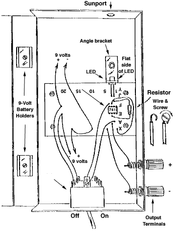
The Sunphotometer case is shown below in figure C4. The hardware and even
the circuit are pictured. This activity is devoted to attaching hardware
to the (video) case.

Figure C4
Sun Photometer
Install the VHS-1 hardware in the case by following these steps:
- Use four 4-40 screws and hex nuts to mount the solderless breadboard
inside the case as shown above in Fig. C4. (Two different sizes of screws
and hex nuts are used. The 6-32 screws are thicker than the 4-40 screws.)
- The rows and columns of holes in the breadboard are numbered. Align
the breadboard so that column number 1 is closest to the rigid side of the
case. Insert the screws through the bottom side of the case. Tighten the
screws and hex nuts with a screw driver and pliers.
- Use a file to remove 1 mm from the end of an angle bracket. Mark
the filed end with a colored marker or pencil.
- Place the angle bracket in front of the breadboard as shown in Fig.
C4. Adjust the bracket until it is 2.25 cm from the inside of the rigid
side of the case. The holes in the bracket will then be aligned with columns
2 and 3 of the breadboard.
- With the bracket pushed flush against the breadboard, mark a drill
guide in the bottom of the VHS case at the center of the hole in the bracket.
- Use a 5/32-inch bit or its metric equivalent to drill a hole at
the drill guide you just marked. Hold the case firmly while drilling. Carefully
use a hobby knife to remove any plastic attached to the edge of the hole.
- Insert a 6-32 screw through the back side of the case and the hole
in the unfiled end of the angle bracket. Place a 6-32 hex nut over the screw.
- Make sure the filed end of the angle bracket faces up. Then press
the bracket flush against the breadboard and tighten the screw and nut with
a screw driver and pliers.
- Refer to Fig. C2 and
measure the exact distance of the center of the upper hole in the angle
bracket from the inside of the rigid side of the case (2.25 mm in the prototype)
and the bottom of the case (1.7 cm). Then mark a drill guide in the front
of the case that exactly matches these dimensions.
- Double check the drill guide you just marked to make sure it is
centered directly over the hole in the angle bracket installed inside the
case. Then use a 9/32-inch bit to drill a hole at the drill guide. If you
don't have this drill bit, drill a smaller hole and carefully enlarge it
with a reamer or hobby knife.
- Install the two 9-volt battery clips on the inside of the flexible
side of the case using 6-32 screws and hex nuts at the locations shown in
Fig. C4. Be sure to insert the screws through
the battery holders and then through the inside of the flexible side of
the case. Tighten the screws and hex nuts with a screw driver and pliers.
- Install two angle brackets on the outside of the case using 6-32
screws and hex nuts. Orient the brackets as shown in Fig.
C3. Be sure the edges of these brackets are flush with the shoulder
that protrudes along the bottom edge of the case as shown in Fig.
C3. (If one or both brackets are not flush, enlarge the hole slightly
so the bracket can be pushed against the shoulder.) Make sure the lid of
the VHS case closes properly. Then tighten the screws and hex nuts with
a screw driver and pliers.
- Remove the hex nuts and lock washers from the two binding posts.
Insert the threaded ends of each binding post into the holes shown in Fig.
C4. Install the black binding post nearest the end of the case. Replace
the locking washers and hex nuts and tighten with pliers.
- Place the solderless breadboard over its mounting holes so that
the row of holes designated 1 is next to the rigid side of the case. Insert
four 4-40 screws through the back of the case and hold them in place with
4-40 hex nuts. Tighten the screws and hex nuts with a screw driver and pliers.
Stop for a moment to review what you have done so far. Are the external
angle brackets flush with the shoulder that extends along the bottom of
the case? Are all the hex nuts tightened? Does the case close properly?
Previous Page || Up
a Level || Index || Next
Page