|
 Hands On Physics Hands On Physics
Haze
Messing Around
SIGNAL AMPLIFIER
|
Overview
This Sun Photometer does not use a standard photodiode for a light detector,
it uses a green LED instead! LED stands for Light Emitting
Diode. As you can see from its name, it is a diode, as is the photodiode.
Although they emit light very nicely, LEDs have a very small response as
light detectors. The tiny response of these diodes needs to be amplified.
This activity shows how to do this with a simple electronic circuit that
uses an important kind of chip, called an operational amplifier, or opamp.
An opamp can be configured to increase the signal (current) from a diode
and convert it to a measurable voltage. This detector and its amplifier
circuit is the heart of this Sun Photometer
Questions to think about:
- Does this detector show selective color response (that is, do they
detect better at some colors than at others)?
- Is this detector linear (that is, does it give double the response
for double the light)?
Materials
To amplify the signal from the diodes, you need to build a simple circuit
on a breadboard.
For this, you will need:
- The breadboard.
- An operational amplifier (741 or equivalent.)
- An assortment of small resistors in the range 1 Mohm to 10 Mohm.
- A pair of 9 V batteries with clips for connection to the breadboard.
- Hookup wire.
- Clip leads.
- A volt-ohmmeter.
Some tips to help you make a circuit that works:
- Attach the batteries last. First wire up everything, check your connections,
then attach the batteries. When done, remove the batteries first.
- Watch out for static. If the air is dry and you notice frequent sparks,
be very careful. One of those sparks will zap the opamp. Work on a metal
surface that is connected to pipes or the ground wire in an electrical socket.
Attach the common lead between the two 9-volt batteries to this grounded
surface. Always place one hand on this surface. Store the opamp with its
legs in black, conductive foam. Transfer the opamp in its foam to the metal
surface before removing it and connecting it to the circuit. When you handle
the opamp, DO touch all its legs with your fingers while your other hand
touches the metal surface.
- Keep your leads short. Run wires and components around the opamp so
you can extract it easily
Activity
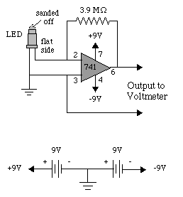
Build the amplifier circuit illustrated below.

Figure M8
Detector Circuit
The opamp is the large triangle. Connect the two batteries in series
as shown and define their common point as ground, symbolized as three parallel
lines forming a triangle. Connect the three ground points together. Also
connect the three p;9 V points and the two +9 V points.
Use a 1 Mohm resistor for R.
The schematic shows numbers for the pins (legs) of the opamp. The following
illustration shows how to figure out which pin is which.

Figure M9
Opamp
Look down on the top of the opamp. You will see a notch or round depression
near one end. The pins are numbered in order counterclockwize from that
point, starting with 1.
This circuit converts the current I that enters its input to a voltage,
V, that appears at its output. The relation between the two is
V = -IR
If you arrange for the current to flow out of the circuit, then that
is considered a negative current and the output voltage will be positive.
Therefore, if the complete circuit is as shown, the voltage measured will
increase as the light level increases.
Reporting
Keep a journal as scientists do, even when messing around. Record all your
questions and observations in a bound notebook. Don't erase, just cross
out errors. Write enough so someone else could reproduce your experiments.
Diagrams can save lots of words and help make your ideas clear. If you make
measurements, record your data, with units. Tables are useful for repeated
similar measurements. To make the logic of any calcuations clear, first
record the formula you used, then show the numbers used to evaluate the
formula, and finally your answer.
Previous Page || Up
a Level || Index || Next
Page